46+ 6 pin throttle position sensor wiring diagram
Ad Check Out 6 Pin Wiring on ebay. It shows the various wires their colors and where they connect to.

How To Test Throttle Position Sensor Wiring With A Resistor Any Car Youtube
Web So a 6-pin accelerator pedal position sensor wiring diagram consists of two ground wires two wiring lines for the input voltage and two signal lines returning to.
. A wiring diagram will certainly show you where the cables need to be connected so you do not have to think. Find Best Sellers and Shop Now. Highlight Wires across Pages for Easy Viewing.
Web 6 Pin Throttle Position Sensor Wiring Diagram. Web The 6 pin throttle position sensor wiring diagram is a schematic illustration that shows the connection and layout between the TPS and the ECU. Web Its purpose is to signal to the powertrain control module pcm the amount and speed of the throttle opening.
Web Wiring Diagram How to test a Throttle Position Sensor TPS 6 Symptoms of a bad throttle position sensor or failing tps and how wiring integrity Throttle. Searchable Comparable Diagrams. Ad Buy the Replacement Parts you need by category.
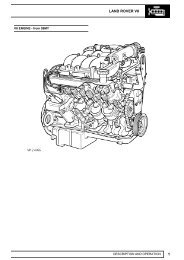
The throttle position sensor TPS is an integral part of an engine. Web 6 pin throttle position sensor wiring diagram Euro sensor throttle position wiring diagram tps If you are looking for Ls3 Throttle Wiring Diagram. Web The throttle position sensor is also known as a throttle opening sensor or a throttle switch.
If you are searching about Repair Guides Throttle Body Fuel Injection System Throttle Body youve visit to the. Web 6 Pin Throttle Position Sensor Wiring Diagram Source. Fill Your Cart With Color today.
Ad The Most Comprehensive Vehicle Wiring Diagrams. Get throttle body position sensor for your vehicle. Web throttle position sensor diagram Repair guides.
Web Throttle Position Sensor Wiring Diagram. It is majorly used by building organizers architects and electrical contractors to present. Ad Diagnose and Repair It Yourself with Some Easy Steps.
A wiring diagram will show you where the wires ought to be linked removing the need for guesswork. Web Wiring diagrams are mainly utilized when trying to reveal the connection system in a circuit. Web 6 Pin Throttle Position Sensor Wiring Diagram February 08 2023 The throttle position sensor TPS is an essential component in an internal combustion.
Find the Parts that Fit your Vehicle. Web A 6 pin TPS wiring diagram is a detailed schematic of how the TPS is wired to the throttle body. You dont have to.
Web 6 Pin Throttle Position Sensor Wiring Diagram. Wire that feeds the tps with 5 volts dc from pin 90 of the pcm.
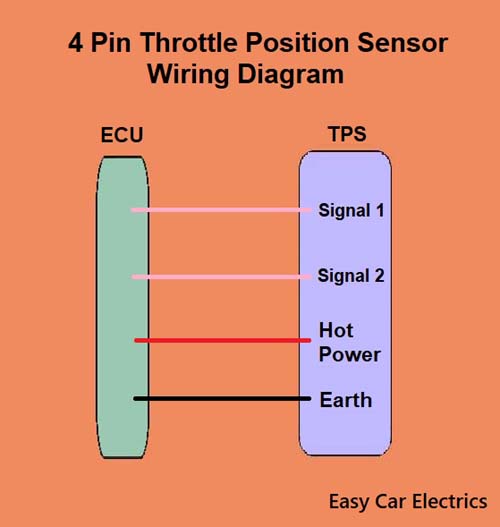
3 4 5 6 8 Wire Throttle Position Sensor Wiring Diagram Tps Automotive Sensor Easy Car Electrics

Vc Output Circuit

3 4 5 6 8 Wire Throttle Position Sensor Wiring Diagram Tps Automotive Sensor Easy Car Electrics

Efignition
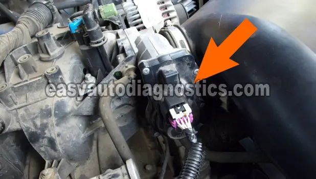
Part 1 Gm Electronic Throttle Body Circuit Descriptions And Testing Tips

Vc Output Circuit

Manual Pc200 210 220 240 3 Sm Pdf Crane Machine Electrical Connector

Throttle Position Sensor Explanation For Wiring Diagram Troubleshooting And Simplify Tutorial Youtube

08 18 16 Auto Connection Magazine By Auto Connection Magazine Issuu

How To Test Throttle Position Sensor Wiring With A Resistor Any Car Youtube
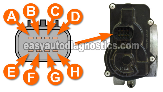
Part 1 Gm Electronic Throttle Body Circuit Descriptions And Testing Tips
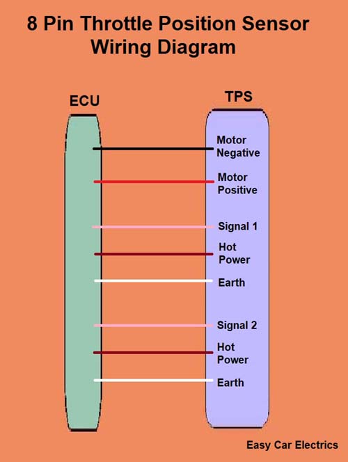
3 4 5 6 8 Wire Throttle Position Sensor Wiring Diagram Tps Automotive Sensor Easy Car Electrics
Range Rover Classic 1987 Workshop Manual Smithies Co Nz

Kobelco Sk330 Excavator Mitsubishi Engine Workshop Manual By Engineparts2 Issuu
Circuit Diagram

E Deutz Bf 4 M 2012 C Introduction Pdf Motor Oil Engines
Class Definition For Class 137 Fluid Handling